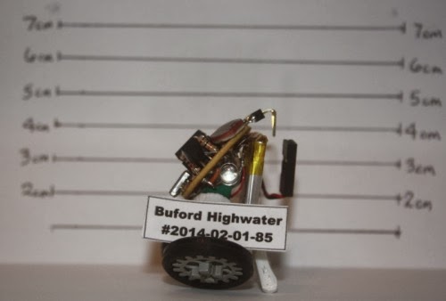
Tuesday, January 7, 2014

Buford Highwater Micro Robot

Buford Highwater

Yeah, that is a silly name for a big bad “Robot” but for some reason it just hit me while trying to piece him together and he’s a tiny fellow anyhow. Buford was really an afterthought when I finished Lilliputian. I had started the original Yahmez MicRObot challengeentry with the concept of a dual ATTiny85 bot, one for brain, other for motors but gave up and used a ProMini clone instead. After looking at the left over parts for a bit I thought surely I can throw something together with these. Besides I had yet to build any actual robot with one of the ATTiny85’s I’ve had for a while.
Update 01/04/2014 - Added Schematic at the Bottom
Buford’s Pants


Buford’s pants are a 3d printed mount found on Thingiverse. I found the part some time ago but never really had a good plan for it. The GM15 gear motors are actually too small for the mount and I didn’t really want to burn time modifying the part so I wrapped them up in some green electrical tape. Once the pants were done I thought a 3.7v 240mah LiPo battery might make a good “backbone” so the hot glue gun came out and he was now upright.
Buford is a pretty minimalistic bot featuring the two GM15 gear head motors mounted in the “pants”, the battery forming the backbone and some small 3D printed “third legs” to hold him up. The wheels are Lego gears and the tires were from Lego as well I believe or maybe somewhere else. For driving the motors a couple 2N2222 transistors were used which allow only forward motion for each side. Seemed the only way to keep things small enough for the platform and is very easy to do.

Buford’s Head
With the 8 pin socket for the ATTiny85 in the middle I sketched out a layout to allow two LDR’s for eyes, a couple transistors to drive the motors, matched up the needed resistors for the LDRs and transistors and then mounted an IR sensors below for his mouth like feature. After digging around for ATTiny85 IR code online and thinking about how Buford was going to be a mute with no sound output as there were no more I/O pins, I decided to change out the IR receiver and put a tiny speaker I had salvaged from an old cell phone. The tiny square speaker mount fits nicely below the Tiny chip and although not loud, provides enough noise to make him a little more menacing… I mean annoying.
The back side of the board is a little messy, especially considering I took the time to draw up and layout the whole wiring scheme, followed it exactly and THEN realized I designed the LDR’s with the resistors going to the input pins instead of to ground. “Face palm” time. That error made me go back, cut up / out some of the wiring and get it right the second try.
To spice up his head I added a couple green LEDs in parallel to his drive motors on the back of the board which glow depending on how hard that motor is being driven. Because the GM15’s are pretty high geared and the wheels/tires are pretty large he is way too fast for his own good so the PWM rate is extremely low and hard to control but he does move at least.
To get power to the board I thought about a few options but did not have a tiny double throw on/off switch that would allow charging the battery in OFF mode so I just added a two pin header, extended it a bit to make it look like “hair” and added a connector to the battery wires. Kind of looks like a pony tail from the back.
I tried to make his board have some resemblance of a “face” with the two LDR’s up top for eyes, the 8 pin CPU for a nose and the speaker for his mouth. No clue what the resistors are, warts maybe. The two transistor kind of stick out there. I had thought about maybe some tiny hands but he looks good enough to me for now.
Buford’s Brain
There’s not much there to start with but he does have 8K of empty space to fill so he can do a few things. He should be able to 1) Track Light; i.e. sit still and rotate to face the brightest until he is balance, 2) Hide from Light; same thing but avoid light, 3)Follow Light; move towards the brightest light until close enough, 4) Run from Light; turn away from the light and keep moving until dark enough.
I started to code up some options for selecting modes by covering up the LDRs, you can pretty easily do three different settings by fully covering up the 1) Left, 2) Right or 3) Both for three options. BUT then I really thought about how easy it is to swap out the ATTiny85 and how many of them I had here so I just changed variables and burned a chip for each mode. I can then swap them out as desired. Not optimal solution but quick and dirty way of making it happend.
So far Buford can track light and follow it in a kludgy but walking like wobble which I actually kind of like and turn away and run away from light. Nothing special for sure. There is still plenty of code space left with the current code taking about 3K of the 8K available. Unfortunately the speaker output is not very loud so trying to make much sound isn’t near as noticeable as I’d hoped. Additionally I guess the ATTiny85 doesn’t support the Tone() function to play musical notes so something else would have to be done to play any type of “music”, if you can call it that.

Parts List
To summarize what makes up Buford here is the summary of the parts list:
2 x GM15 motors
2 x Lego “Gears”
2 x Rubber tires off something
1 x 3d Printed “pants”
3 x 3d Printed rear supports (only two needed but I tried a tripod setup that didn’t work)
1 x 3.7v lipo battery
1 x 1” circular perf board
1 x 8 pin ic socket
1 x ATTiny85 (or more if you want to program up various modes)
2 x 10k resistors for LDR
2 x LDR devices
2 x 2N2222 transistors
2 x 1K resistors for transistors
2 x bright green LEDs
1 x cell phone speaker
2x 2 pin 90 degree header pins
1x 2 position female pins and header
1x pull your hair out soldering session on the back to make it work

Wow, ok, there are a lot more parts there than I thought but it’s still pretty simple

Closing

So there is Buford Highwater. Only took about 8 hours on and off total messing with ideas, code, etc to put it all together. I obviously reused code from my other bots for the base code, just stripped out all the other libraries and music functions that were not needed.

So he’s Buford, he’s bad, and he’s big… well, no, he’s actually tiny… ATTiny too but he’s still a menace.


Stay out of trouble Buford!

Update 01/04/2014 - Schematic
Maxhires has asked about the schematic and driving the motors etc from the ATTiny85 so here's how I did it. I'm sure there are btter ways out there but this does work. Notice I am driving the little speaker directly from a pin. I've done this for all my bots with sound without issues but remember these are tiny speakers so I would guess lower current.

Lilliputian Micro Robot

Lil·li·pu·tian
n.
A very small person or being.
adj.
1. Very small; diminutive.
2. Trivial; petty.

Updated 01/02/2014 - Added in progress pics at bottom

Lilliputian - seems like a pretty good description of this little fellow. Trivial, petty, diminutive, very small, etc. With all due respect to Swift’s Gulliver’s Travels of course. Inspired by Yahmez MicRObot challenge, this is my 2.0 attempt. The first attempt is still there and maybe viable for a future finish but I like this 2.0 layout much better. I just packed in as much as I could WITHOUT resorting to surface mount devices (SMD) which I have no skills with.

 
Size Matters

 
At least in the challenge so first I guess I should outline the current size of Lilliputian. Currently the bot is about 35mm wide by 50mm long (not including the bumper horns) and 35mm tall. Total weight is 34 grams (1.2 oz). Not tiny by any means or as compared to some other entries I guess but small for me. I gave up some size for features which was the plan from the beginning.


Chassis and Motors

 
Lilliputian features a 3D printed base chassis of my own simple design to mount the two GM15 micro motors. To keep things narrow I offset the motors and wheels giving it a bit of a goofy stance but making it much narrower than traditional back to back mounting. That is where some 90 degree gear motors such as those recently sourced by Yahmez would be quite handy. For wheels, I used a couple old mouse wheels that I had kept. It took a bit of work to clean out the middle to allow mounting and they are definitely crooked and poorly mounted but they have stayed on so far.

 
For speed control a L293D chip was used and was soldered up “dead bug” style. Without an inverter it does eat up six output pins to control the two motors but I figured I had plenty of pins in this situation. Two pins are used to control motor direction for each side and a pin is then used to drive PWM for each side.

 
However, the GM15 motors are really geared a LOT higher than I thought there were and the tall mouse wheels really push the speed of the bot beyond usable levels. The balance between enough PWM to move and too much while cruising is a challenge. Some better coding would be helpful as Yahmez suggested to maybe ramp up the power to get rolling and then settling it down for cruising speed. Something to work on later I guess.

 
I designed the chassis to use basic Pololu QTR encoders with striped disk on the wheels. I’ve done this before with larger sensors but not this small. I thought the Pololu QTR-RC sensors would work as they are small and since I didn’t read the datasheet like a fool I put the thing together and could not get output from the sensor. More reading revealed that you need to use the library to read the sensor as what makes them digital is the small cap that must be charged and then read using the same I/O pin. That will NOT work with driving an interrupt pin for encoder reading. I even tried making my own timer interrupt routine to go read the sensors but could not get any consistent output. Since then I have purchased the QTR-A sensors which are pure analog but have not tested if they can transition enough to drive a digital interrupt pin. Plus the fact that the wheels are glued to the output shafts and the wiring is on the opposite side there is no clean way to replace the existing encoders so that part of the bot is on hold.

 
Power

 
Powerwise a 3.7v lipo with onboard electronics for under / over voltage protection was mounted on the bottom side. It’s easy to get to and replace in case it bloats from overcharging and tucked up underneath quite nicely. However, everything on the bot is 5v so I used a Pololu step up / down regulator to turn the 3.xV into 5V. I believe the current limits are 500ma but it appears to be fine for my needs. Pretty sure I could not have run a ping sensor along with everything off that current but this thing is too small for such a sensor anyhow. I couldn’t find a switch that was small enough in my junk pile so I just used a three pin header for power and changing needs. I use a header jumper to power it up and a three pin connector for the charger. I used a wall wart charger that came with a little quad rotor and it appears to have some current limiting in it as well and has charged the battery without issues. The battery is a 240mah LiPo version but driving the speaker appears to really eat up power so run time is not impressive. Fun, just not impressive.

 
Brain Power

 
Originally I really thought I would go with one or more ATiny85 CPUs for this build but seeing the ability to mount up a ProMini 328 I changed direction as it is still my favorite Arduino CPU to use since it’s so small with full 328 capabilities and memory all in a 24 pin DIP. Instead of building a undershield or perfboard this time, I simply glued the CPU to another little mount I designed and printed that also mounted the wheel encoders (that do not work as noted above). I then soldered wires directly to the CPU instead of using header pins. Messy but seems best at this scale for me.

 
Sensors and Stuff


IR Receiver
I added an IR receiver to allow controlling the bot and his “modes” with a standard remote control. Each mode can be selected from the remote including RC control, autonomous mode, and some special entertainment type of functions. The IR sensor mounted on top of the AtMega chip on the ProMini quite nicely in my opinion. For now I’ve used an existing remote from a Toshiba stand alone DVD burner I had in the workspace but any remote could be used as it is quite easy to add IR control to a bot. I used to think that would be a challenge but with the IR library it’s very simple.

 
The remote is primarily used to change the “modes” of the robot from roam, light seek/avoid, light track/hide, “wag”, bark/attack, line follow, etc. It can also be used to drive the robot around with the arrow and navi buttons if desired.

 
IR Transmitter
Since I could not get the encoders to work, that freed up pin 3 that is used for the IR transmitter library so I stuck an IR emitter on the right rear of the bot. Thoughts are he can eventually communicate with SBot or something like that. Nothing is coded yet but maybe later.

 
LDR Light Sensors
Sensors are rather simple with two LDR’s for light measurements. Good news is the LDRs work well. Lilliputian can sit still and track light, turn away from light, and follow or run away from light. He also makes little bleepy sounds when he’s not happy with the light balance as he sees it. Bad news is my light follow code isn’t overly developed so he can get confused and start spinning in place rather easily.

 
QTR-RC Line Sensors
The line sensors do seem to work well using the Pololu library and can easily detect light, dark, and edges. BUT doing so in a fast enough manner to get a timely response from the platform has been a bit of a challenge so far. Additionally my chassis design leaves some to be desired as the offset wheels make it quite easy for the bot to do a “wheelie” when taking off which confuses the front mounted line sensors into thinking it has seen an edge so it stops, backs up, takes off and repeats the loop. Not good. I ended up mounting a small piece of Lego jewel in the back corner to stop the wheelies helping the edge detectors to function.

 
Bump Sensors 
Without sonar Lilliputian is pretty blind so I added a small bump switch up front. I can’t remember where these little switches were scavenged from but they are pretty handy little things that take very little pressure to turn on making them good sensors for a small bot. I think they were out of some old tape backup drives or something. Without whiskers they are pretty limited but does give some sensing to back off, turn and continue on at least.

 
Light and Sound
I always like my bots to make a bit of light and noise since I’m easily bored so a piezo speaker was salvaged from an old PC motherboard as recommended in the shoutbox and mounted on the rear. A cycling multi-color LED was mounted up front that adds a LOT of colorful light, in fact a bit too much so I added code to turn it on/off via the remote control. With the little speaker Lilliputian can play a few songs and act out or dance a bit.

 
Feature Set

 
Lilliputian currently has the following modes and features:

 
Roam mode 
Not overly useful but wanders around bouncing off things, avoids black lines if the line/edge avoid flag is set. Line/edge can be turned on/off with the remote as needed.

 
Light Track mode
In light track mode Lilliputian sits still and turns toward the brightest light source he can see at the time. If it’s too bright or you get too close to him with a flashlight he will back away from the bright light making a little noise. Again, in this mode he doesn’t drive anywhere forward for light, just sits there.

 
Light Hide mode
Just the normal inverted light seek mode but again sitting still and turn away from any light source until he is happily balanced. This really doesn’t mean find the darkest point, just turn away from any brighter light source.

 
Light Seek mode 
In light seek mode, Lilliputian follow the brightest light using the front LDRs for balancing. This works best when pointing a flashlight at the front allowing light control of Lilliputian. He will follow the brightest source he sees and once things are bright enough he will stop. If you make things too bright he will back away from the light.

 
Light Avoid mode
Again standard light avoidance routines, run away from the light. In this mode if he finds a dark enough situation he will stop as well and wait for any light changes.

 
Race mode
Just a silly little setup where he counts down with blips and takes off at full speed for a second or two. Just like in real racing, sometimes he crashes trying to go too fast. Once done he sings a little tune and spins in place having enjoyed the thrill.

 
Wag mode
Another silly one borrowed from SBot. Just wags back and forth for you.

 
Bark / Attack mode
Another silly little routine from SBot where he drives forward, makes a barking/noise sound and retreats.

 
Line Following mode
Lilliputian is really not well versed in line following yet. He can “usually” follow the line but with the high speed, bad code, and having to check for IR inputs, etc he can easily miss the line and take off running away. Even when following the line he is pretty jerky bouncing around trying to stay on course. But he can make it around a normal line sometimes.

 
HokeyPokey mode

 
Apparently he learned this routine from my TED robot I guess. One of the most important routines he plays the song and does the moves the best he can. Seems like he is having fun at least.


Future Feature Set

 
Maze solving - Really want to have it run the maze, store path, and re-run it… someday

Things that Didn’t Work
Wheel Encoders
Obviously the wheel encoder setup didn’t work as mentioned above. This may be resolved
through a different encoder but that will have to be for another bot someday.

 
Onboard Compass
Originally I really wanted to drop a small HMC5883L compass module I had on the bot. I tested the module on the bench and it worked pretty well. however, mounting it up on Lilliputian proved to kill the usefulness of it as mounted down by the CPU the compass does not work apparently from the RF interference of the CPU or maybe the magnets of the motors underneath it. I have built a small stand off to allow the compass to work but not really crazy about how it looks so not included here.

 
Closing Summary

 
So big plans scaled down for the most part. Original goal was wheel encoders, dead reckoning navigation, compass directional controls, Light sensors, line following, maze solving, IR controller, little monster. Reality is a neat little platform but not all the bells and whistles I originally had desired.

Oh well, one can’t hope for too much out of a Lilliputian unless there are a lot of them right?

No, I’m not building a lot of these things - too small for my patience :-)


Update 01/02/2014 - Added some early Pics

Per Lumi's request, here are a few early on pics. Unfortuately I didn't take many in process pics like I should have.

Raw printed chassis that I designed. Very simply base platform and two tubes to hold the motors.


Chassis loaded up with the GM15 motors and mouse wheels/tires.


Mounting the CPU up top. You can't see the mount which is just a tube with a flat piece on top to mount CPU.


Top view before CPU mount. The step up regulator on the left, H-bridge dead but up front.
Initially I was going to try using an LED and a couple LDRs for line follow. Bought sensor instead.


This is the best view I have of the "guts". Before line sensor install but you can see the wheel encoder attempt.
Pretty packed in but generally functional. I still think the right encoders would work.
Wouldn't be high resolution but could be useful.

Thanks for all the comments and encouragement all!

Monday, November 4, 2013

We Have Print

We Have Print

 
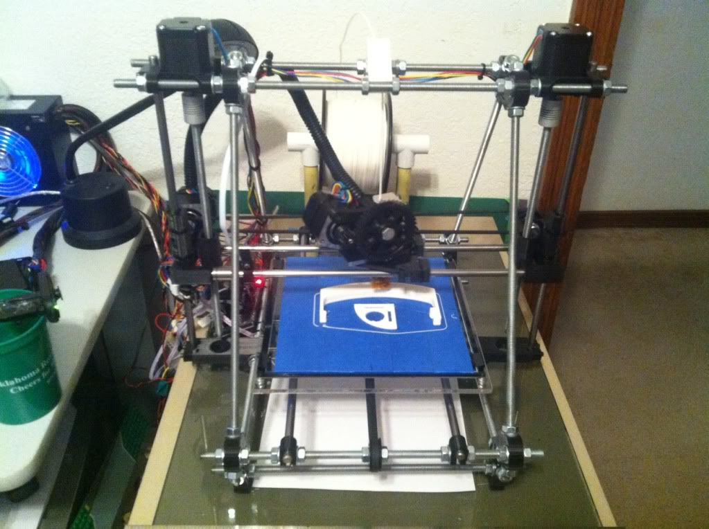
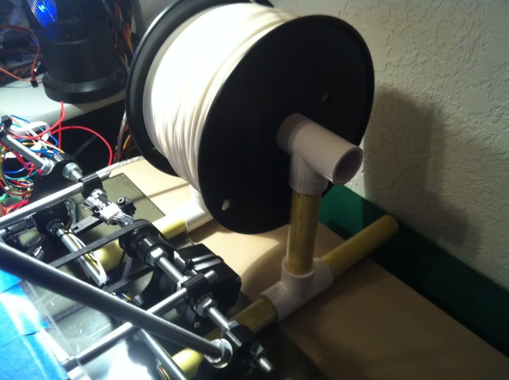
After the little delay in getting filament, it finally arrived from the new vendor. In the mean time I had almost forgotten that I need something to hold the spool so I scrounged around in the garage and found a bunch of leftover PVC T’s from my compressed air piping runs in the garage but had no PVC pipe left over. So I started looking around and found a sacrificial  broom whose handle fit nice and snugly into the PVC T’s A few 4.5” cuts later (btw, broom handles are much easier to cut that M8 rod :-/ ) I had a stand that should handle both the larger and smaller rolls of PLA.

 
Final Checks and Test

 
Before printing I went through the final checks again; bed level check, re-home everything, reviewed the whole printer and loaded up the PLA. the first thing was to finally check out the extruder and make sure it will work. I used the Pronterface default 185C setting, although recommendations from LMR experts would lower that later. Clicking on the Extrude button in the lower right of Pronterface pushes out the plastic. One thing I had read was to measure the amount extruded against the set amount in Pronterface which was 5cm. Sounds easy but on each extrude the output curls back up on itself making it hard to get a good idea. I finally pulled the curled up piece off and straightened it out to measure. It’s a little over 5cm but maybe I’m stretching it pulling it off?

 
Test Print #1

 
With all apparently in place, I figured I’d try the nickel test part to start with. It’s small, flat and provides some idea if you are on scale or not. First print, first fail. It tried to print but the very first failure was having the 1.75mm filament jump out of the hobbed bolt channel and run it’s way off the facing bearing. Nice. Not bad though. So I think maybe it’s a fluke and load everything back up and try again. Nope. Not only did the filament move off the bolt BUT the bed nuts that I thought lock washers would hold spin lose and the bed is too tight creating more issues.

 
So back to bed leveling and looking for a guide solution for the filament. The bed nut issue was simple, do what everyone tells you to do and put a dab of nail polish on each nut/thread when you’re level. Did that and done. The other issue wasn’t quite so simple. How to keep the 1.75 in the channel. I figured there were a few possible reasons; 1) I didn’t get the clamp bolts tight enough, 2) I didn’t tighten them evenly so it walks out one side, or 3) the hobbed bolt is really for 3mm and it’s just not a sharp enough cut to hold it in the center. So just to make sure and get a clean print, I retightened the bolts trying to get them even but the bolt issue was so easy. To test a guide I cut up a small piece of aluminum, slotted it and servo taped it to the extruder.

 
Ran another test print and it worked! You can see that item #3 looks pretty good for a 3rd print try. Testing the nickel fitting the slot didn’t go so well though. About .381mm off or .02% is what we calculated. Instead of making major changes I thought I’d try a cube of box to check outside dimensions so I printed a 2x2x1cm box. Outside dimensions were slightly LARGE so 

I’m not sure if I have a scale issue. Jinx, ossipee and hoff agreed that maybe there is too much filament being extruded so it’s making everything slightly fat. The default setting was 300mm/min so I backed it down to 275 for future tests.


In the mean time I wanted to print a few “fun” parts just because, those that didn’t have minute scaling needs so I loaded up the most impressive part to me, the beer can handle! Cool, nice, big print to test too. Load / Print / Fail - Extruder jam. Ok, better try a smaller part and get this extruder thing resolved. I went back and thought I’d really tightened it down, maybe it’s still just walking out because it’s not tight enough. So I tightened it, and tightened it and finally squashed the filament so it wouldn’t feed either direction. Not the solution.

 
Think Smarter

 
So the filament is drifting off / out of the bolt groove, maybe a better inbound alignment. I’m sure there is something else going on here as even when I was assembling the extruder I wasn’t really happy with the loose feel of the whole thing. But since I can’t fix that right now, how about a better feed guide? I found one online that snaps on top of the extruder but it didn’t really go down any deeper than my existing aluminum one. Think Protowrxs, think… Ouch, that hurt.

 
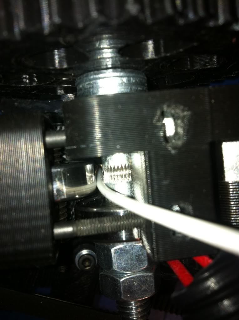
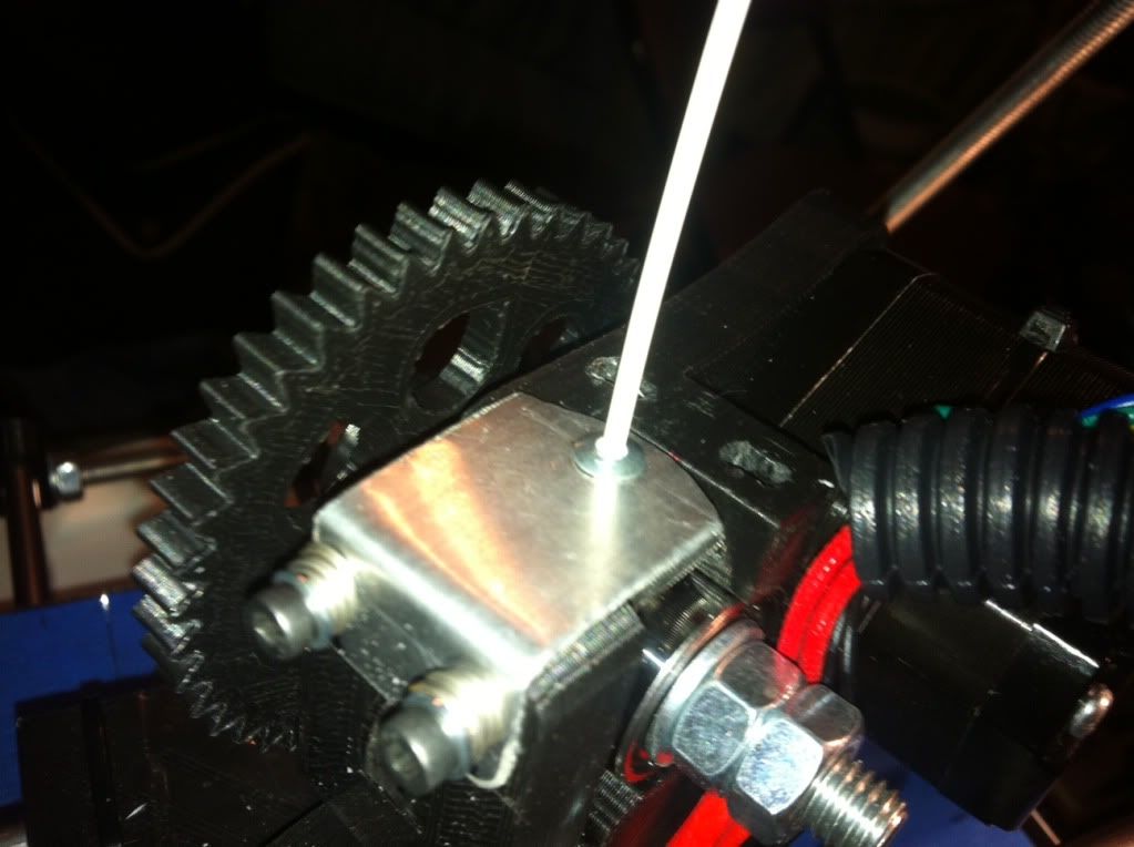
Digging around in the garage again I started thinking I need a small tube that can go deep enough into the extruder right down to the hobbed bolt to keep the walking to a minimum. Small tubes were abundant but none had any good mounting options. Then it hit me to try a
small pop rivet housing. I found one the right length and the filament fit in there just perfect. Wow, dumb luck. I knocked the riveting piece out and make a new more stable guide top, pressed the rivet into the hole and found a small nylon nut that I slightly drilled out to press fit on the bottom side to hold the rivet in.

 
It Works

 
So back to the big beer handle print, why not. Loaded it all back up, test extrusions, re-home, cross fingers and print. This time I watched it, and watched it, and watched it keeping an eye on the feed the best I could. By now it was getting late and after about half way through it was still working so off to bed and leave it be.

 
Results

 
The next morning low and behold a handy dandy beer can handle was done and a pretty clean print as you can see here. There are three locations where there is extra filament dangling around. They are consistent all through the layers so I’ll have to start researching what can cause that. The handle is slightly smaller than the stl measurements so I DO some scaling issues to fine tune.  Overall I have to say I am very happy with the output so far. I know it’s only day two of printing but I was pretty concerned it would be weeks before getting this working. Partly dumb luck, partly good assembly, but mostly good help from the LMR printer experts willing to share and assist a newbie.

 
Fine Tuning

 
So it was printing but as I noted it was still not perfect scale. The nickel doesn’t fit through the hole and the big beer can holder I made worked but was super tight to get it on a can. Obviously things are slightly too small. How to fix? Ossipee explained the process to me and I had already looked at the steps per mm settings in the configuration.h file in Marlin, but I still wasn’t exactly sure which direction to make the change, although it is obvious now. Instead I found another calibration site similar to the one that Birdmun had provided me a link to. What I liked about this one located here:http://mendelmax.com/RepRapCalculator.html, is that you just plug in the disired size, what you measured on your output, what your current configuration is and it calculates you a new number to plug in. So I plugged in my settings and measurements, obtained the value and updated the firmware. Much better.

 
Go Big

 
As ossipee recommended from the beginning, it may look fine at small scale but the real test is to “go big”... and fail likely in my case but none the less that is needed to get it right. So the next step from to reprint something bigger to see if the scale works and then re-adjust as needed. So needing a correct size beer can holder I re-printed it using the new scaling. Results were I ended up with too much scale at that level so re-calculated with the big scale measurements and re-print again. Pretty much the process. Of course you don’t have to print the whole thing, let it lay down enough layers that you can measure and stop the print, pull it and re-check / re-tune.

 
Experience

 
So beside some more really fine tuning the printer is working. It wasn’t too hard overall. I liked the mix of hardware of building the printer, especially since I’m a mechanical bicycle/goKart/motorcycle/car kind of guy at heart. I also like the electronics/software side of things and learning the basics of how it works, maybe because I’m an IT/coder/manager professional.

 
Other Resources: