Wednesday, October 23, 2013

3D Printer - Progress

Assembly Continues

My hardware kit was supposed to have the needed metric cap screws, washers, nuts, etc for a Prusa I2 build but since there are many different iterations of the I2 it really wasn't complete. I found a couple additional kits of 25 pieces of M3 screws and picked up some different 10mm, 15mm, and 25mm lengths to have during the process. With the needed screws on hand I could try to move froward with more assemble.

JerZ to the Rescue

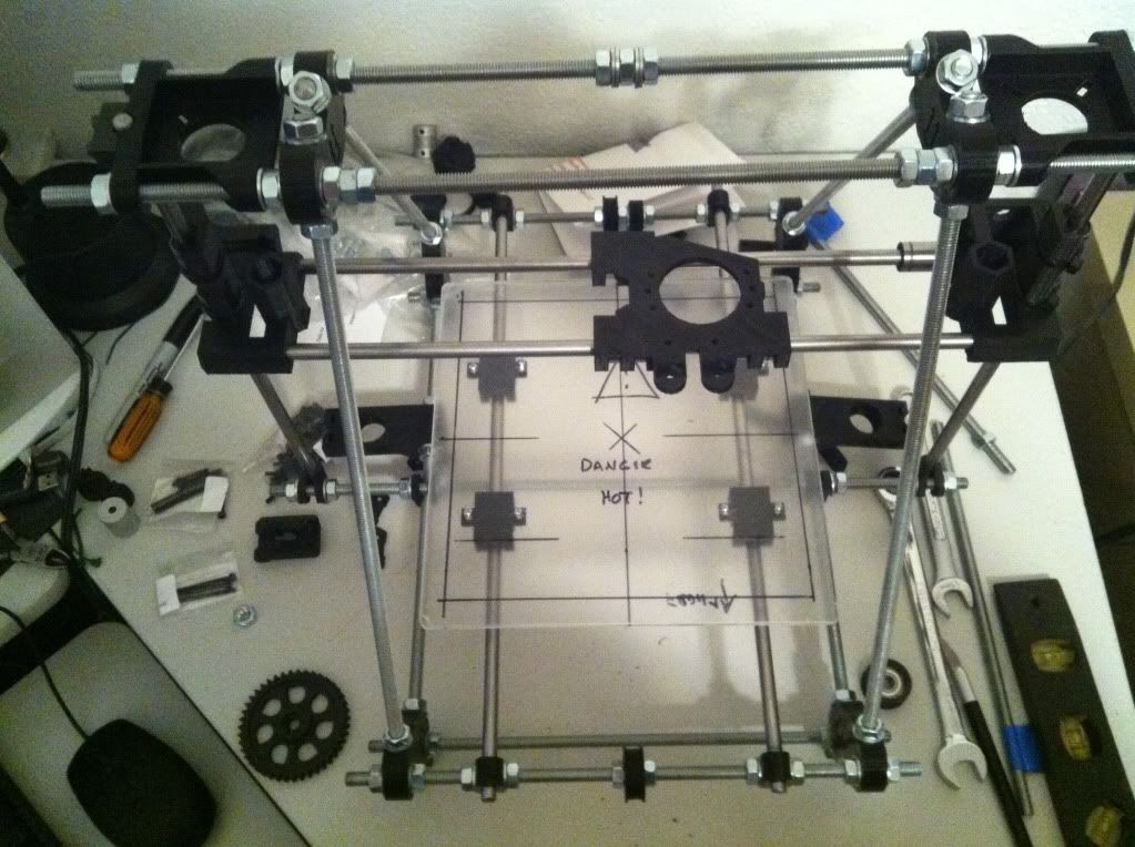
Although my parts kit came with some lower Z stabilizers, it did NOT come with the plastic caps required to use them. The kit had two caps that are used on the top of the Z smooth rod but nothing for the bottom. After discussion in the LMR forum, it was advised to NOT use the stabilizer bearings and instead let the threaded Z rods dangle in the air allow some end movement. The point is that if you lock the ends down and the threaded rod isn't perfect, you will get X Axis movement that will create print errors.

For me, I really liked the method that the Z smooth rod end mounted down low making it much more likely to keep the rods parallel so JerZ offered to print up a couple end caps that were missing and mailed them to me. The worked great and it was much appreciated! This removed the extra wide lower center threaded rod and cross bar clamps and the need to make a lot of adjustments to keep the Z rods parallel. That's what I think anyhow.

Step Step Step - Steppers

The stepper motors move the print bed forward and backwards, the head carriage left and right and the whole head assemble up and down. X/Y/Z - three planes and you have 3D. The recommended steppers for many printers are "NEMA17" units but of course I found out quickly there are many variations of them online. Different voltages, holding torque, some with D-shafts, others without, and on and on. Once again to keep it simple I searched specifically for 3D printer ads to try to at least narrow the choices down some. I also have some good input from birdmun in regard to selecting steppers with connectors at the motor.. which you can see in the pics I did NOT follow and may ultimately wish I had. His point is if you have socketed steppers you can more easily swap one out if you have an issue or dead motor. Very true, guess I'll be cutting/splicing wires if something happens.

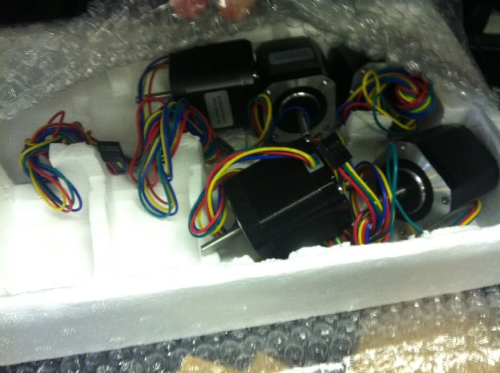
After looking/poking/questioning around I locked down on a set found on ebay that are NEMA17, 76 oz-in holding torque, 4.2v, have the D Shaft, and are 1.8 degrees per step which I believe is the correct specs for what I'm doing. The actual part number is KL17H248-15-4A. They do NOT have sockets at the motor but they do have nice 750mm leads on them making it much easier to route the wiring back to the electronics.

"Some Clearancing May Be Required"

You see this with most printed printer parts you find online. Basically it's saying "Hey, these are printed parts, they are pretty dang close but you have to cut on them some to make them work". And cut on them I did have to. The worse areas were the 3mm nut capture areas that the nuts just would not fit into. Exacto knife skills saved the day but be warned, it's still easy to split parts due to the layered method of printing. I also just smoother some of the edges up, cleaned up stray strings, etc to try and make it all work and look a little better.

This was especially true on the extruder build and I did split out a couple parts slightly. I used some superglue to fill in the split and hope that will resolve any long term issues.
Another issue was getting the extruder Hobbed Bolt, the bolt that has a grove in it and ribbing to grab the plastic filament and push it through the extruder. The area where the head is supposed to fit into was pretty nasty in the print so I had to clean it up and try to make things fit. After that I still couldn't get it to fit at a perfect 90 degrees to the gear so I had gear wobble. It meshed ok, but I didn't like the wobble so the suggestion was to heat up the head enough to kind of melt it into place and 90 degrees position. Used a butane lighter, a little heat and it seems to have works. You can see the head doesn't quite fit into the socket on the gear though here. It's solid but I think I'll drop a bit of super glue in to make sure. I bought two hobbed bolts to have a spare so even if I move to a herring bone gear set I have a bolt.

The hobbed bolt is another part that could have been built at home I guess. It's a basic 8mm bolt with a notch and ribbing done on it but for $12 I found two online with the nuts and washers and figured it would take me longer to try to do it myself than $12 worth of time.

Hot End
To melt the plastic and get it down to the sub millimeter stream needed to print something, you need a "hot end". After research, reason, and lots of input from LMRians I went with the tried and true J-Head design. Since I picked mine up on ebay it is likely some knockoff but should work. It has a 0.4mm output, was supposed to be able to use 3mm or 1.75mm filament and had the heater and thermistor already installed and setup. I also had to get a mounting plate to hold it in the carriage and extruder. Hot end in hand, moving on. I had already ordered some 3mm black filament so I decided to do whatever was needed to make the J-Head use that size filament as I could tell it was setup for 1.75mm when I got it. After pulling it apart and discussing with hoff70 it became apparent that the head was MADE for 1.75mm but COULD be drilled out for 3mm. Looking back I can see the ad for the unit said THEY will drill it out for 3mm if you want before shipping. So another minor setback, can't use the 3mm filament I have now but the recommendation was to go with the 1.75mm size. It is supposed to be better/cooler/tighter/etc anyhow. So I coughed up some more money and ordered some 1.75mm black and went ahead and ordered some red as well as I really didn't want to be stuck printing black for too long.

Getting There

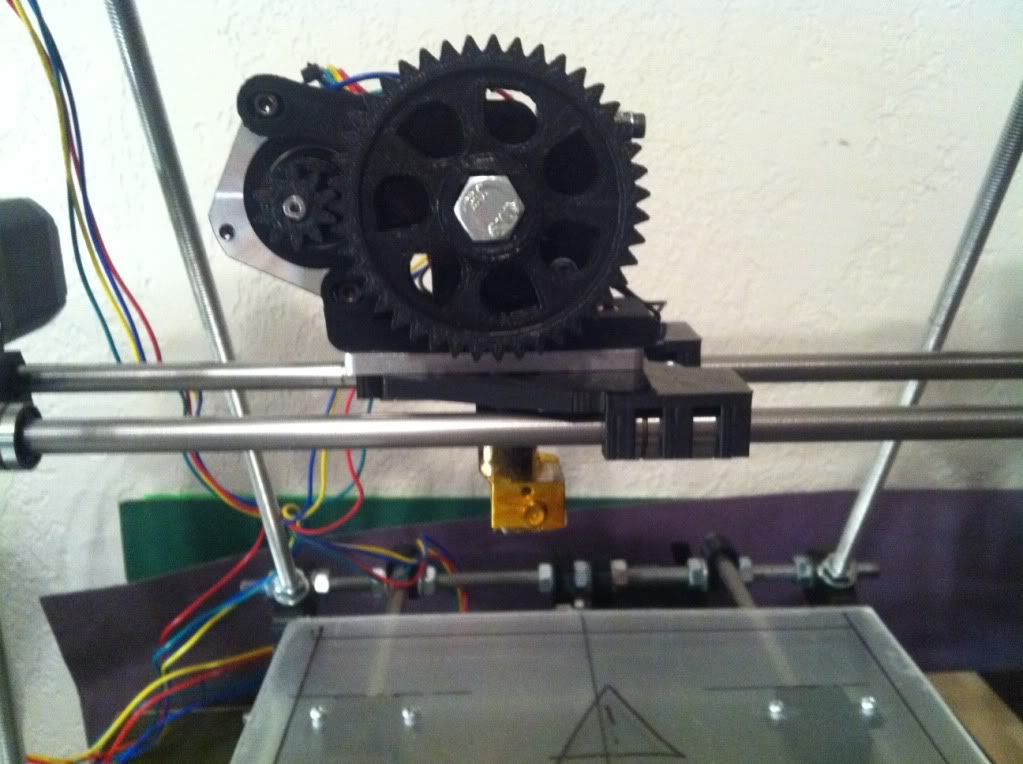
With the extruder together and the recently purchased hot end in hand, I finished mounting the extruder to the carriage. Still no belt on it but wanted to make sure it all fits together, belt route clear, etc before doing that. One thing again about clearance work, be care and make sure the nuts fit in the captures. The but was a little tight on one side of the hot end mount and forcing it in created another small layer split.

With the extruder on the carriage I checked the movement back and forth and although tight I believe it is working as it should.

Mounting Steppers

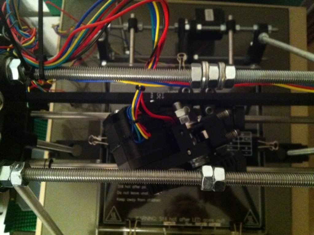
Mounting the steppers is really pretty straight forward. I just needed to make sure I used the correct length cap screws that weren't too long but not too short either. Some clearance work on the mounting slots and they fit just fine. There is now a mass of wires going nowhere but I'm not routing anything until I have the electronics in hand and plan where to mount it all.

With the Z Axis motors in I hooked up the CNC aluminum couplers that connect to the Z threaded rods. These seem much better and isolating any threaded Z rod imperfections but with anything there are those who say don't use them as well. Some say they will sag/stretch over time affecting the Z axis. Maybe so but they seem to much better than a hard clamped mount that comes with the original parts kit. I think with some continuous tune ups and system checks any sagging can be adjusted out as needed.

The Print Bed

A very important piece that needs to be right is the print bed. Although many get great results from printing on anything, I figured I need to build what I want up front. With that in mind, I included a heated print bed in my kit so I could print ABS later on if desired, but also it seemed like the easiest way to mount a nice thin setup. For the base, I used some 1/4 acrylic that I picked up at the local hardware store. I noticed that many use it as their base as it's flat, easy to cut, and just looks nice. After I cut it out to the basic size, I did hear from some on LMR that you need to protect it from heat if you are mounting a heated bed as it can warp. Figures.

So with a nice piece of acrylic for the lower bed mount, I ended up covering it up with some classic Mr. Gasket exhaust gasket sheet that I plucked from my garage and my car hobbies. This stuff can handle hundreds of degrees so it should protect the acrylic  from the heat bed. I even mounted with the Mr. Gasket logo up top just for the heck of it.

I also picked up some small springs at the hardware store to use to mount the heat bed/glass on for adjust-ability as many have done. I could have used ball point pen springs but these are similar and should work fine.

Belted

Next up was to get the belts on for the X and Y axis. I mounted the Y axis bed belt first using the included belt clamps but also use the trick of using small zip ties to hold a loop at the end of each belt and then one to tighten those loops together so you can pull the belt tight with the zip tie before tightening down the clamps. Worked well for the bed and I had smooth motion to and fro.

The X carriage setup wasn't quite as easy as there is not enough room between the two clamps to do the zip tie method. For this I clamped down one belt end and then left some extra length on the other end allowing me to pull it tight and clamp it down. Carriage moves left and right fine without any issues!

Extruder Mount
Next was the final mount of for the extruder and hot end on the carriage. After putting the extruder in place and starting the screws another problem arose. With the longer, higher torque, stepper motors, the motor extends backward into the path of the belt creating interference. At first I wasn't sure what to do besides get a short stepper for the extruder but after pulling it back off I found the angled mount holes that allow mounting the extruder slightly sideways. Mounting it like that clears the belt in the back but it does make the motor hit the threaded rod on the left side before getting to the edge of the print bed. Oh well, will have to do and limit switches should keep any interference at bay.

Summary To Date

So at this point the chassis is built, lower print bed mounted, steppers mounted, extruder and hot end mounted, all axis are moving properly manually and I've started routing and organizing wires. I've also labeled all the steppers with my label machine. Electronics are here so last steps are finalize bed leveling setup with springs, wire up the heat bed eventually along with the thermistor for that. More to come!


Monday, September 30, 2013

3D Printing... Attempting...

So with so many LMR (http://www.LetsMakeRobots.com) enthusiasts building, buying, printing, or renting 3D printers I figured I’d jump on the bandwagon and go along for the ride. I can really see the joy in being able to just print cool things off ThingiVerse much less the thought of designing some little mount, feature, cover or whatever for a robot you may be building.


Fear Factor


Having watched those who have built printers in the public eye like Hoff70, DanM, (others?) and seeing the vast list of options, printers, versions of the same printer, options on top of options for existing printers, and all the other confusing stuff that swirls around the 3D print world, I was quite leery of getting my feet wet, much less diving in headfirst and risk breaking my neck… or pocket book.


However, after a while of reading, watching, and listening to all the builders like Jinx, TinHead, and others and reading through a couple build manuals online it seems to have slowly come together into something I can finally being to grasp. Sure, the basics are simple, print head (and/or bed) moves in X/Y/Z manner while print head drops a precise amount of melted plastic or other material into a particular shape. Easy enough.. but then you start hearing GCode, PronterFace, Ramps, Sanguinololu, Skeinforge, PrintRun, send.py, and a million other speciality pieces of the process that at least I had no clue what they were or what they were used for.


Fortunately the LMR shoutbox is quite often full of 3D friendly people and just watching the conversations there, AND using the Internet for everything they said I didn’t understand I started to see that I could eventually make some sense of it all. At least enough to put something together and get started.


But Which One?


Of course, when you start looking you’ll find there are LOADS of different printers, versions, and obviously price ranges. For my first build I really wanted to get something large enough I’d be happy with but Uncomplicated enough that I could (hopefully) get it working and tuned well enough for quality prints. I looked a few options from the EventorBot, that looks nice and simple but apparently it’s kickstarter founder is no longer answering questions at this time, a Prusa Mendal Max that looks nice and sturdy but requires more specialized metal parts, a Rostock with it’s cool movements but circular print area, and a few others.


After asking around in the LMR shoutbox again most were saying for simplicity sake and easy tuning go with a Prusa model so I narrowed down on the RepRap site for options. After checking out the options there the Prusa Mendel I2 seemed to be the most popular and still should provide a good platform. It was actually kind of difficult making the final decision on which direction to go, I guess due to the time and money that will be invested, but likely just my uncertainty of what it’s all about.


The Plan


Having made the decision to go with the Prusa Mendel i2 I dug head long into what options there were. Buy a kit of all the parts? Buy a pre-assembled one?  Source out the parts separately? Or what the heck else. Although very likely buying a pre-assembled one or even a full kit may be the best bang for your buck, I decided to piece my own together from various sources and see if I can save any money and still make it work. Plus the treasure hunt for parts seemed to appeal to me anyhow forcing me to learn more about what are the best pieces to use or at least the most popular. It also lets me break the whole thing down in phases allowing it to smoothly fit into my budget.


After reading through more assembly manuals I found online I finally got a basic parts group figured out and dropped it all in a spreadsheet to review options, prices, etc. I really ended up just breaking it up into Rods, bearings, metric hardware, printed parts, extruder, hot end, electronics, power supply, steppers and pretty much “other” with estimated prices on them all.


I also had some enlightening discussions with other printer owners about going 8mm metric or keeping it easier to get parts by using 5/16 SAE rods. Although I could save a few bucks on the 5/16 stock, I decided for a first timer I better stay the course and stick with a known so I’m going with the metric setup.


Off We Go


So armed with a list and estimated prices I headed online to eBay, MakerFarm, SainSmart and others planning out my purchase route. The first steps are getting the basic frame built so I looked through options for rods, metric hardware, printed parts, and linear bearings. I also ran across some 5mm x 8mm couplers that looked like a better option that printed and picked them up as well as some metal stepper gears and GT2 belts. The rods, printed parts, and hardware arrived I spent an afternoon assembling it all. I chose an un-cut rod kit so quite a bit of time was measuring and cutting threaded and smooth rods to the right lengths. I also polished the smooth rods with some 1000 grit wet sand paper hoping to get things as smooth as possible. Note in the pic above the carriage is on backwards - fixed it right after that pic.


So What’s Next


As noted I broke the project down into three phases of which the first has been spent. The next phase will be for Steppers, Hot end and mount, skate bearings, Hobbed bolt, bed plates, etc and other misc items. After that will be the final electronics which I believe I am going with a SainSmart kit to keep it all together using Ramps 1.4, A4988 driver, Mega2560, end stop switches, heated bed, cooling fan, and a nice large LCD / Controller setup. The LCD/Controller should have an SD card as well for future computerless prints.


Software

As noted before, there are many different hardware configurations but the most confusing part for me was the software options out there. Everything from what CAD app to use to create or view parts to the controller versions and PC interfaces are all foreign languages at this time. I ended up finding this site to guide me through it all for the first try. http://www.nextdayreprap.co.uk/reprap-downloads/ I liked their walk through from the very basics of downloads through install and testing. I know there are some newer versions of the pieces out there but for now I plan on getting it working using their guidelines and then worry about possible version upgrades if warranted.


I’ve already worked through the download and installation process they have listed and have PronterFace running on the laptop I plan on dedicating to the printer interface. It doesn’t have anything to talk to so it may not be a good install but it looks cool on the screen. :-)


Upgrades


Of course browsing around ThingiVerse is not necessarily a good thing to do, even when you do NOT have a printer yet. I’ve already found several “upgrade” pieces I’d like to print for the printer itself once I get it working and tuned up. Things like a simple spool holder, filament guide, filament dust filter, bracing, fan holders, integrated Z motor mounts, etc. along with many cool robot pieces like Basile’s cool wheels, pan/tilt parts, and of course the BoB robot. Print, print, print! Of course I’ll have to print a few hundred small cubes along the way to get things working right.


The Future

It may take me a few months to get it hacked altogether and moving around but I’ll keep plugging along and posting updates as the project moves forward, or backwards.